Design intent.
Process reality.
Forming simulation, DFM and die design for stamped parts: engineer the part and its manufacturing route together, from the first geometry review to the first measured part.
The problem
Where programs lose time.
Geometry that can’t be formed
Design intent outruns the material’s forming limit.
Late tooling changes
Feasibility issues surface after steel is cut.
No feasible process
The part needs a forming sequence nobody has defined yet.
How we work
From geometry to a proven route.
Define the route
Connect the blank or tube to the final part through a feasible sequence of operations.
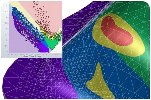
Simulate forming
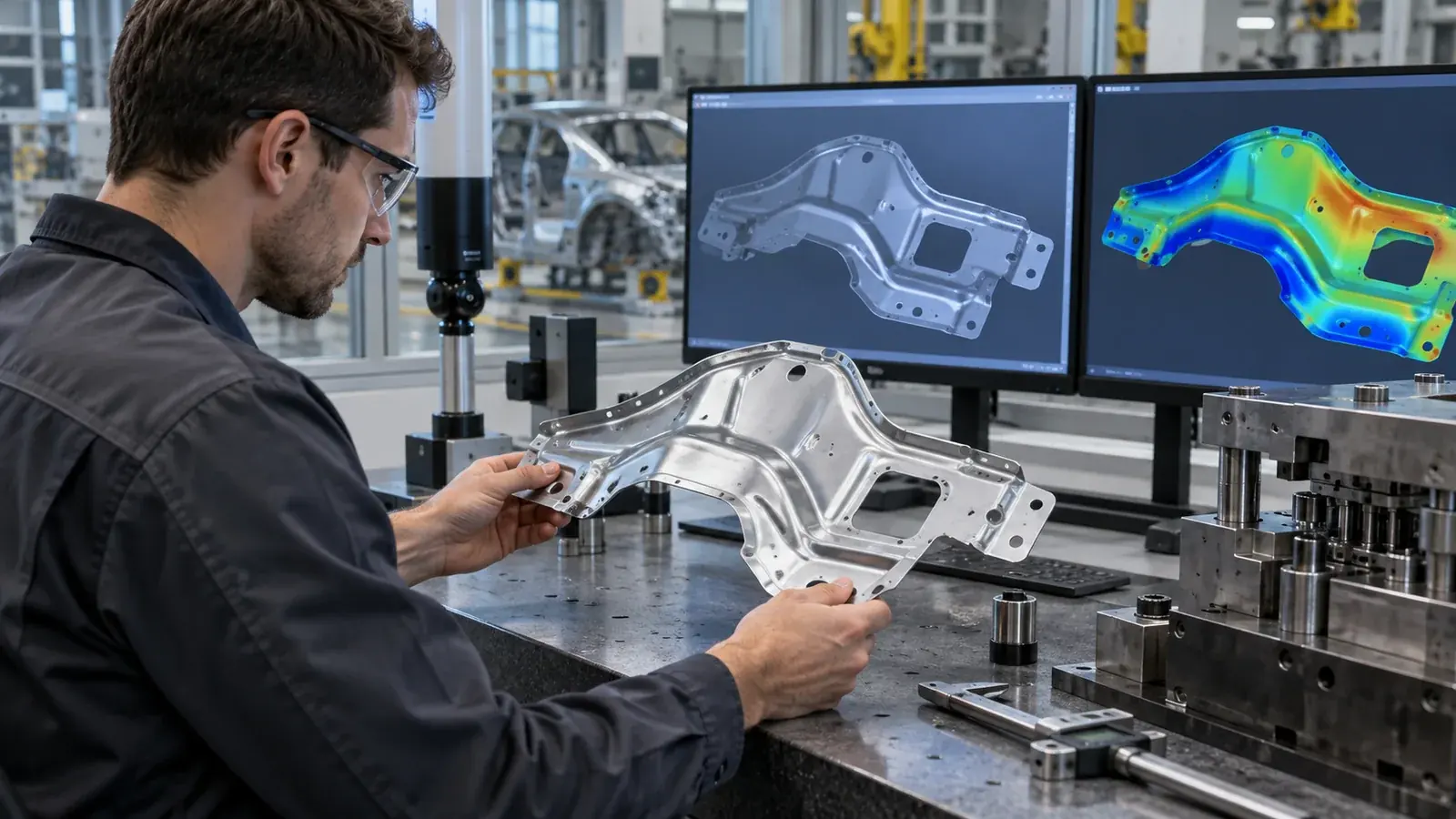
Expose thinning, splits, wrinkles and springback before committing to tooling.
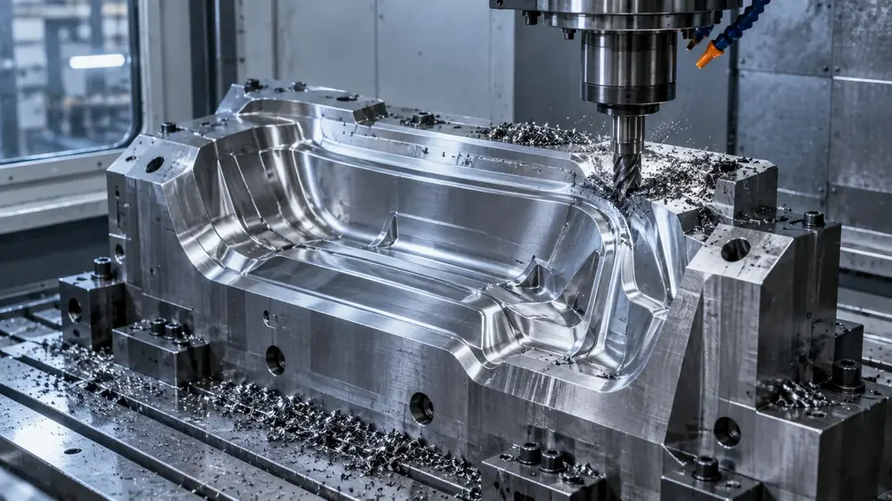
Refine tooling
Develop die surfaces around material flow, restraint and springback compensation.
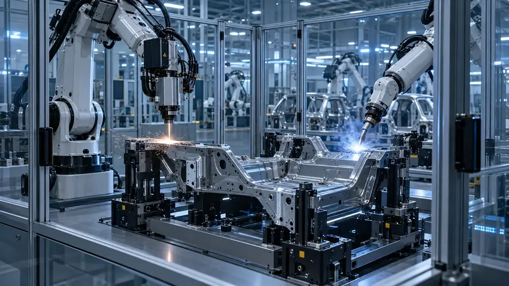
Plan downstream
Define trimming, joining and fixturing around the formed part.
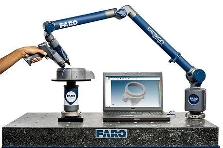
Measure
Compare physical parts with nominal geometry and the simulated result.
What you get
A route your tool shop can build.
Included services
DFM review
Geometry, material and tolerance changes that make the part feasible.
Process sequence
Forming, trimming and joining steps defined for the part.
Tooling concept
Die design connected to the process, ready for build and tryout.
Simulation results
Formability and springback findings with recommended revisions.
Send the CAD. And the target.
The part, the drawing or the manufacturing challenge. We scope the development around the decisions your program needs to make.
Start a project